
Delamination, Disbonding, and Porosity Are Not the Same Inspection Problem
Similar looking ultrasonic responses can come from very different changes in a composite structure.
A 12 dB amplitude reduction in a composite does not identify the damage mechanism. It identifies a change in the acoustic response.
That change may be associated with an interply delamination, a bonded-interface separation, distributed porosity, a thickness transition, local laminate architecture, curvature, coupling, or another feature that changes how ultrasonic energy moves through the structure.
This is where composite Ultrasonic Testing becomes considerably more demanding than simply finding an area that looks different on a C-scan. The display may make the result look obvious while the physics underneath it is not.
For an experienced technician or Level III, the useful question is not only where the response changed. The useful question is what physical change in this particular construction could have produced that response, and whether the technique retains enough information to support that conclusion.
The Laminate Is Already Part of the Signal
A composite laminate is not an acoustically neutral path. Fiber orientation, ply sequence, resin system, fiber volume fraction, laminate thickness, cure condition, local build-up, curvature, surface finish, and manufacturing process can all influence velocity, attenuation, scattering, and waveform shape.
That means the sound-material response is not background information to be ignored. It is part of the inspection model.
A response that is normal in one region may be anomalous in another. Ply drops, doublers, tapered laminates, bonded repairs, core transitions, potted regions, inserts, edge closeouts, fastener reinforcement, lightning-protection layers, and local thickness changes can alter the ultrasonic response without representing damage.
Before defect classification begins, the expected response of the undamaged construction has to be understood. In complex aerospace structure, that may require more than one sound-area baseline because the construction itself changes across the scan area.
This is also why a technically clean calibration does not automatically make interpretation simple. Calibration establishes the performance of the inspection system against a known condition. Interpretation still requires the technician to understand what the production part is doing acoustically.
A Delamination Creates a Through-Thickness Interruption
An interply delamination introduces a separation within the laminate. From an Ultrasonic Testing standpoint, that creates an additional interface in what would otherwise be a continuous through-thickness acoustic path.
If the separation is sufficiently open and favorably oriented, a strong portion of the incident energy can be reflected from that interface. Less energy then reaches the material below it. Depending on the acquisition strategy, the result may appear as an intermediate reflector, reduced backwall amplitude, loss of backwall response, a time-of-flight change, or some combination of those effects.
Depth matters. A shallow delamination can compete with the initial pulse, front-surface response, ring-down, or dead zone of the transducer and instrument combination. This is one of the reasons that we typically use fixed delay line transducers, immersion, bubbler, squirter system, or other water/modified immersion delay means, A deeper delamination provides greater time separation from the entry surface, but the signal has also propagated through more attenuative material before reaching the discontinuity and returning.
The practical problem becomes more complicated when impact damage is involved. A low-velocity impact can produce matrix cracking, fiber damage, and multiple delaminations at different ply interfaces. The shallowest strong reflector can partially or completely shadow deeper damage. A plan-view C-scan may therefore provide a defensible projected damage area while still failing to describe the complete through-thickness damage architecture.
Gate placement is not a housekeeping detail in that situation. A gate optimized only for backwall amplitude can show where transmitted energy has been interrupted, but it may hide useful information contained in intermediate reflections. A technique intended to estimate delamination depth has to preserve and evaluate the time-domain information needed to do that.
A Disbond Changes a Designed Interface
A disbond presents a different acoustic problem because the separation occurs at an interface that was intentionally created as part of the structure.
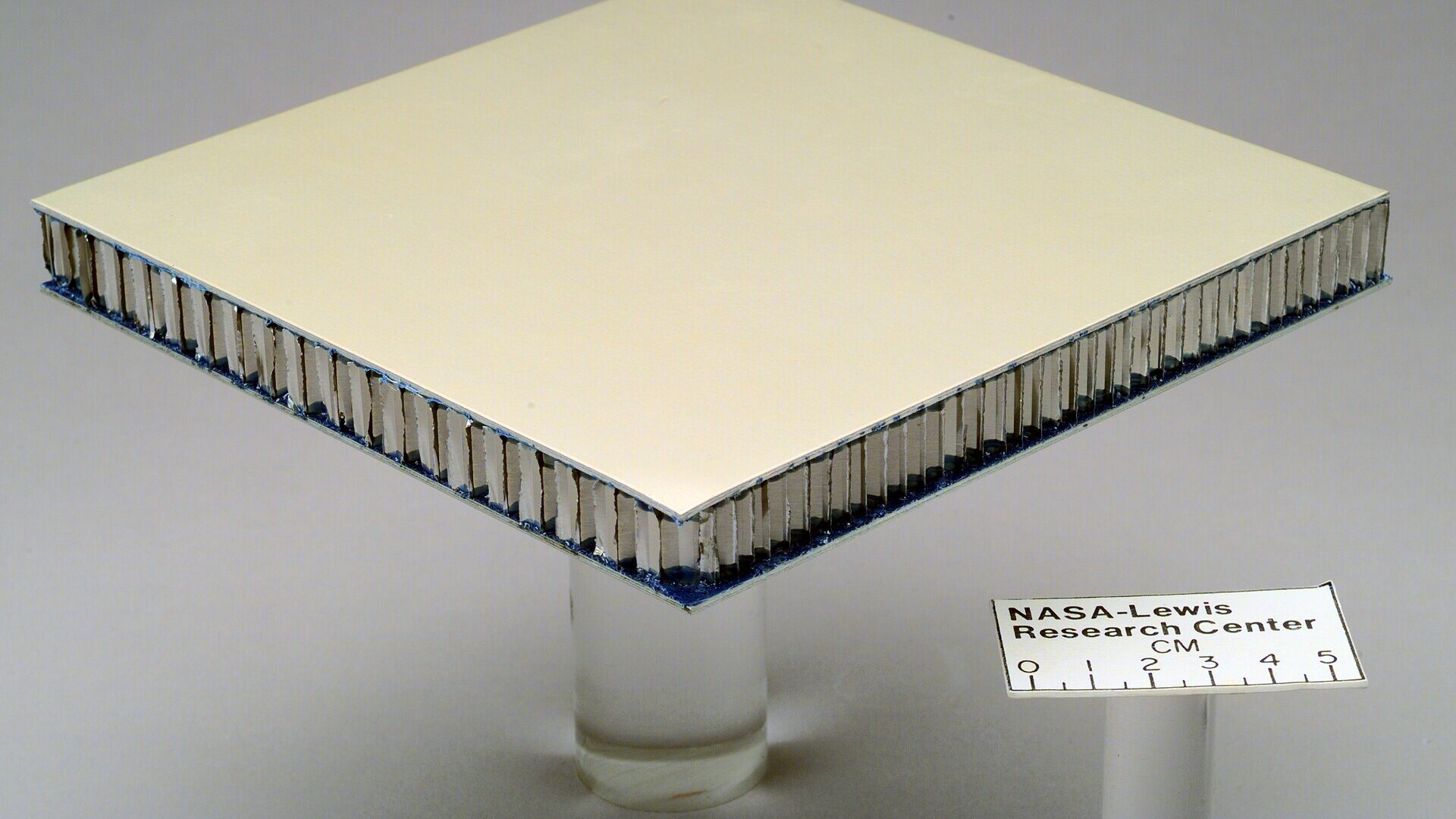
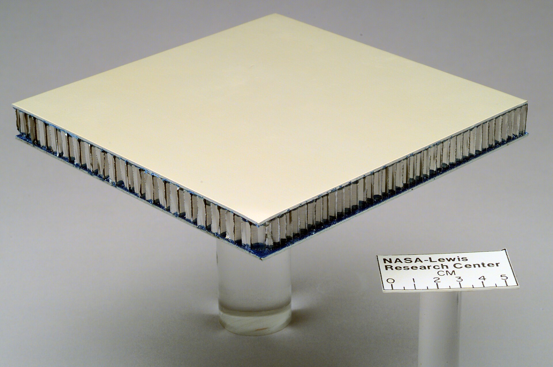
Consider a carbon-fiber facesheet bonded to honeycomb core. Even in sound material, the ultrasonic field interacts with the facesheet, adhesive system, core geometry, and any subsequent interfaces in the acoustic path. The baseline is therefore construction-dependent before a disbond is introduced.
Core cell size, core material, cell orientation, facesheet thickness, adhesive distribution, local potting, core splices, inserts, closeouts, repairs, and transitions between solid laminate and sandwich construction can all change the local response.
That is why there is no universal signal shape that can be called a disbond without structural design and manufacturing context. What matters is the demonstrated change from the expected response of the particular bonded construction being examined.
Probe footprint also becomes important. If the effective acoustic footprint is large relative to the cell dimensions, the received response can contain contributions from multiple portions of the core geometry. If the probe is moved across the panel, cell position beneath the probe can influence amplitude and waveform behavior. A dense encoder index does not remove that effect because encoder spacing and acoustic spatial resolution are not the same thing.
A technician who establishes a single reference response and assumes every amplitude change elsewhere represents bond loss can produce a very convincing map of normal construction changes. The map can be repeatable, stable, and still be wrong in what it claims the response represents.
Porosity Does Not Behave Like a Planar Reflector
Porosity changes the ultrasonic beam in another way. Instead of introducing one relatively coherent planar interface, a porous region contains a distributed population of small voids or gas pockets within some volume of material.
Those discontinuities can increase scattering and attenuation throughout the affected thickness. Backwall amplitude may decrease. The reflected response may decrease. The noise floor can change. Waveform coherence may degrade. The response may develop gradually across an area rather than producing the sharper boundary often associated with a discrete planar separation.
The distinction matters because the same amplitude loss can be produced by different mechanisms. A backwall reduction caused by a delamination is not physically equivalent to a backwall reduction caused by distributed porosity, and neither is automatically equivalent to a loss caused by coupling or local geometry.
Porosity evaluation can also be strongly frequency-dependent. Increasing frequency can improve sensitivity to smaller-scale material variations, but it also increases the difficulty of maintaining usable signal through thick or highly attenuative laminate. The frequency that produces excellent results on a thin panel may leave very little usable backwall response in a thicker quasi-isotropic layup.
This is one reason porosity assessment should be treated as a material characterization problem rather than simply a search for a discrete reflector.
Reference Standards Are Part of the Acoustic Model
A reference standard does more than provide a place to set gain. In composite Ultrasonic Testing, it represents an acoustic model of the production structure.
A programmed discontinuity in a thin laminate does not automatically demonstrate equivalent detection capability in a much thicker laminate. A skin-to-core disbond standard built with one facesheet thickness, adhesive system, and core configuration may not represent another sandwich construction adequately. The same nominal discontinuity size can produce a different response when depth, material architecture, or acoustic path changes.
Porosity is even more sensitive to this issue. Converting an amplitude or attenuation change into an assumed void content requires a defensible correlation to the applicable material system, laminate thickness, fiber architecture, cure condition, frequency, and reference population. A generic dB loss should not be treated as a universal porosity percentage.
A technique can therefore be properly calibrated and still have an unrepresentative reference basis. That is a technique-development problem, not an instrument problem.
The C-Scan Can Hide Important Information
C-scans are powerful because they turn a large encoded data set into a spatial image. They can also remove information from view.
The displayed color normally represents one selected measurement parameter within an acquisition gate. That may be peak amplitude, time of flight, thickness, transmitted energy, or another derived quantity. The image is therefore a visualization of the acquisition logic, not a photograph of the defect.
Two areas with the same C-scan color can contain very different A-scan behavior. One may contain a discrete intermediate reflection. Another may show progressive backwall attenuation. Another may contain unstable coupling. Another may correspond to a known structural transition.
When only the processed image is reviewed, those distinctions can disappear.
For encoded work, the underlying waveform data should remain available wherever practical. Significant anomolies, amplitude-loss regions, unexpected boundaries, and responses near known construction changes should be evaluated in the raw ultrasonic data rather than classified only from the color map.
High data density does not eliminate interpretation. It increases the amount of information available for interpretation.
Projected Area and Damage Architecture Are Not the Same Quantity
Composite impact damage illustrates the problem particularly well.
Several delaminations at different ply interfaces can overlap when viewed from the inspection surface. The C-scan may show one connected projected area even though the internal damage consists of multiple planes at different depths, with matrix cracking and fiber damage between them.
For some engineering evaluations, projected plan-view area is exactly what is needed. For others, the depth distribution or relationship to a bonded interface becomes important. The inspection output has to match the physical quantity being claimed.
This is a subtle but important discipline. A C-scan should not be asked to prove more than the acquisition and analysis method actually measured.
What Should Be Established Before Calling the Indication Anything?
The strongest composite techniques begin with an expected acoustic response and a defined decision path.
What should the sound laminate look like at this thickness? What should the relevant bonded interface look like? Which response changes are expected from normal construction? Where do ply drops, core transitions, potted regions, inserts, closeouts, doublers, and repairs occur? How does flaw depth affect detectability? Where does signal-to-noise begin to deteriorate? What data is retained for later waveform review?
Those questions should be answered before a colored region is assigned a defect name.
This does not mean every indication requires laboratory analysis. It means the technique should have a defensible reason for associating a particular signal behavior with a particular physical condition.
That is the difference between defect classification and color recognition.
How Focaltek Applies Composite Ultrasonic Testing
At Focaltek Inspection LLC, composite Ultrasonic Testing is developed around the acoustic behavior of the actual construction. Laminate architecture, bonded interfaces, thickness transitions, core configuration, expected damage morphology, available access, reference-standard response, frequency, gating strategy, spatial resolution, and the underlying waveform data are treated as parts of the same inspection problem.
The objective is not to produce an attractive C-scan and assign defect names to colored regions. The objective is to establish why the response changed and how confidently that change can be associated with the condition being evaluated.
A delamination is evaluated as an interruption between laminate plies. A disbond is evaluated in the context of the designed bonded interface and surrounding construction. Porosity is treated as a distributed material condition whose ultrasonic response may be governed by attenuation and scattering rather than one discrete reflector.
That distinction becomes especially important around honeycomb, repairs, inserts, tapers, multiple damage depths, and construction transitions where a simplified inspection model can produce a convincing but incomplete answer.
Focaltek combines advanced acquisition capability with Level III technique development and experienced data interpretation so the result remains tied to the material physics rather than only to the display presentation. The equipment records the response. The technical value comes from understanding why the structure produced it.
Technical References Consulted
ASTM E2580-24, Standard Practice for Ultrasonic Testing of Flat Panel Composites and Sandwich Core Materials Used in Aerospace Applications, 2024.
NASA JSC PRC-6501, Rev. H, Ultrasonic Inspection of Composites, 2026.
NASA, NDE Methods and Capabilities Handbook: Resources for the Composites NDE Community, NTRS Document 20205002325, 2020.
NASA, NDE of Composite Honeycomb Face Sheet Bonding, NTRS Document 20200003306, public NASA technical presentation.
NASA, Ultrasonic Detection and Identification of Fabrication Defects in Composites, NTRS Document 19930021667.
